You would like to accurately measure a position or a movement. Which encoder is right for your application? And how do you make a choice? Optical, inductive and magnetic systems can be found on the market. Each technology has its own specifications and properties, and these determine whether an encoder is suitable for your application. And if multiple technologies fit your application, which solution should you choose? Our 10 questions will help you select the right technology for you.
Machines often have a built-in encoder to register and regulate positions and movements. In the past, optical encoders were very expensive and inductive encoders were quite large. But times have changed. Nowadays, the models available are more compact, lighter, faster and more accurate. These are important features, because users are increasingly placing higher demands on their systems.
How do you select an encoder?
How can I best measure a certain movement? And which technology do I need to do that? Sean Ram, Account Manager at Sentech, hears these questions often.
“First of all, I investigate what type of company it is and to which degree they are able to realize precision assemblies. Can the machines be produced to tolerances of one tenth of a millimeter, one hundredth of a millimeter or one millimeter? I also ask about the type of machine and the area of application. For example, an agricultural machine doesn’t usually need an extremely accurate encoder, but it does require a solution that is impervious to contamination.”
Ram continues, “In addition, I would like to know what the customer wants to achieve with the measurement. Then, with this aim in mind, we determine the specifications for resolution, accuracy, repeat accuracy, speed and integration options,” says the Account Manager.
It’s easy to specify the very best requirements. But do you really need those? “It is possible for the sensor to solve a great deal of the complexity. This can have significant consequences for the available technologies, with the associated performances and price. Together, we search for an optimal design – performance vs. integration price. In this collaboration, the customer knows his system best and we at Sentech know the sensor market and the possibilities like no other.”
How incremental encoders work
Before we delve into the differences between optical and inductive encoders, let’s first discuss how they work. Incremental encoders work on the basis of a ruler. In the case of an optical encoder, that could be a glass bar with traces of chrome or an aluminum strip with etched lines.
As the encoder moves over the ruler, the sensor counts up or down. The accuracy depends on the quality of the ruler. “The more precise the lines have been set, the more accurate the system is,” clarifies Ram. “MicroE, the brand that we use a lot, develops and produces optical encoder systems. They produce rulers whose lines vary by only one micrometer over a distance of one meter.”
An inductive encoder uses a configuration of coils. The largest generates a high-frequency magnetic field under the sensor. This field induces a voltage in the receiving coils. A copper trace on the ruler modulates the field, which is immediately detected because the receiving coils emit a different voltage.
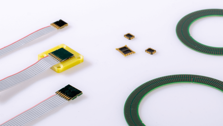
Inductive encoders consist of wirewound coils or smooth coils in a multi-layer printed circuit board or in a silicon chip. Sentech often selects the inductive systems from POSIC. This Swiss company uses the last option for its coils.

Differences among encoders
In general, optical encoders achieve the highest resolutions and accuracies. For example, the encoder systems from MicroE can achieve a resolution of 1.2 nanometers. Inductive encoders are somewhat less accurate than optical systems.
“If you create a well-defined environment with strict tolerances, you can achieve a resolution up to 50 nanometers with POSIC,” Ram continues. “My experience is that a half to a quarter micrometer is relatively easy to achieve. Do you need a higher resolution or higher degree of accuracy? Then we investigate with the customer whether another technology is more suitable.”
Contamination
As opposed to optical encoders, inductive systems have properties that optical technology cannot match. For example, inductive encoders are insensitive to contamination. Even if the ruler is full of grease, dust or damp, the measurement is reliable.
“With an optical encoder, a greasy fingerprint can produce an erroneous measurement,” explains Ram, the Account Manager. “Optical encoders are often used in the semiconductor industry, where there is no risk of contamination because they are used in controlled environments.”
This does not mean, however, that optical encoders are not an option when contamination is involved. Ram shows that there are solutions for these cases: “If we place the ruler upside down, no contamination sticks to it. Shielding the encoder system can also be an option. Once, we incorporated the ruler and the sensor in a duct that we held at excess pressure. Air leaked out of it in a controlled manner, so dust could not penetrate.”
The right encoder in 10 questions
To come to the best suitable encoding system, you must first know what you really need. These 10 questions will help you do this.
-
Which resolution does your application require?
Determine what the resolving power must be. Resolution is the smallest step that an encoder can display. Is a resolution of one micrometer enough for you, or do you require a nanometer range?
-
How accurate must the encoder be?
Investigate what is important for your application: absolute accuracy or repeat accuracy? Absolute accuracy is how much the measurement deviates from the actual movement. Repeat accuracy is a static measure that indicates how great the spread of the measurement is.
-
Which maximum speed is required?
Learn more about the speeds that your machine achieves. The controller of your machine must be able to handle the output of the encoder. The maximum speed influences the choice of encoder and its integration.
-
What are the integration tolerances?
Identify the tolerances within which the sensor and the ruler can be integrated. The maximum allowable alignment errors of the sensor head in relation to the ruler differ for each technology.
-
How large may the sensor be?
Look at the available space. Based on this, determine the maximum size the encoder system may measure and which integration options are available.
-
How contaminated is the area of application?
How much dust, grease, damp, metal splinters and other dirt is present in and around your application? Contamination is a key factor when selecting an encoder. For example, an optical encoder is more suited for a clean environment and an inductive encoder works effortlessly even in a contaminated environment. How an encoder is integrated can also limit the contamination of the system.
-
Is vacuum involved?
A vacuum environment involves two factors: heat dissipation and outgassing. Because sensors cannot easily release their heat, it is important that they generate as little heat as possible. Outgassing can lead to the precipitation of undesirable materials on critical process components. Solutions are available for both factors, depending on the system requirements.
-
What is the temperature range?
Check the environmental temperatures at which the application is used. It is also important to know how long a certain temperature is present and which delta causes the temperature to change. For example, extreme temperatures can influence the choice of technology.
-
Are there any magnetic fields in the area?
If the encoder is placed close to coils or permanent magnets that generate induction fields, this can influence the measurement results. But this is not the case with every encoder system. Fortunately, there are certain types of inductive and optical systems that are less sensitive to this.
-
What is the output signal?
Which type of output signal do you require? Examples are an A-quad-B, index, limits, digital protocol, or sin/cos signal.
Now you know which criteria play a role in the selection of the right encoder. Note, however, that these 10 questions are only one part of the factors that determine which encoder fits your application.
Our infographic also helps you with your encoder selection. Find out which technology suits your application best.
Compare optical and inductive encoders using this infographic.

This article was published in Mechatronica&Machinebouw nr.7 2019 and is written by Alexander Pil
.png)